Trouble-Free Operation for Float Valve Selection and Installation
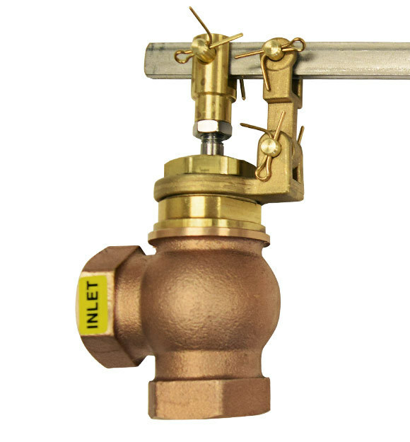
- Ensure that the valve, stem and float used are rated for your maximum inlet pressure and GPM flow rate. Check minimum stem length and minimum float ball size. This may vary according to your application and maximum inlet pressure.
- All BOB® and Bobby® assemblies are shipped standard with the minimum recommended stem and float sizes for reliable and accurate liquid level control up to the maximum rated pressure. Sometimes you can use a shorter stem with a larger float or vice versa; however, not all combinations are reliable at all pressures.
- Ensure that the valve body, disc, cup, stem and float materials are compatible with the temperature and type of liquid controlled.
- For non-standard assemblies, if you see that the float is completely submerged without shutting off, or if the float "bounces" all by itself without stopping, it usually means that the float is too small or the stem is too short to work reliably at that pressure. If your particular application requires a shorter stem, bent stem and/or smaller float than recommended, it will reduce the amount of leverage or buoyancy available to close the valve, thus lowering the maximum rated inlet pressure. A pressure regulator can be used to compensate for a reduction in the inlet pressure. Instead of modifying the assembly or installing a regulator, Control Devices, LLC recommends selecting a smaller standard assembly that fits your available space, or a smaller orifice size to gain reliable shut-off at higher pressure. Please note, by reducing the inlet pressure or selecting a smaller orifice size the GPM flow rate will be reduced. To avoid a reduction, consider using two smaller valves instead of one larger valve to meet both your GPM and space requirements.
- Increasing or decreasing the inlet pressure at the valve will often cause a slight increase or decrease in the water level setting at shut-off. The water level, at shut-off, reaches maximum height at the maximum possible inlet pressure provided; therefore, when the inlet pressure changes, the amount of change in the water level is related to the volumetric displacement of the float. This is a normal property of float valves. Maximum accuracy and repeatability is obtained when the inlet pressure remains constant. If varying inlet pressures are expected, be sure that your application design allows for slight changes in the water level at shut-off.
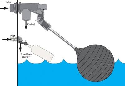
- Always ensure that the float valve is mounted rigidly with respect to the water surface. If the tank wall, supply pipe, or mounting bracket is able to flex or move, it may cause the valve to vibrate, oscillate or "sing" very loudly. As the valve starts to close, the pressure increases, causing the valve body to flex away from the water surface. When the valve body moves away, the valve opens wider and the pressure decreases, causing the valve body to flex back to its original position. At this point, the valve body starts to close again, creating a cycle of oscillation. A rigid mounting system prevents the potential for this kind of vibration or oscillation to occur.
- The tank or reservoir should always include provisions for some kind of overflow drain system capable of handling the maximum GPM flow rate. Dirt, physical damage, excess pressure, loose or improper adjustment, normal wear, or mineral deposit buildup over time may prevent the valve from fully closing. An overflow drain system will prevent the possibility of unexpected flooding, should this occur.
- To prevent overflow during normal operation, the overflow drain should be high enough above the set water level to accommodate the water level at your maximum inlet pressure and allow for any surface turbulence. For closed loop pump systems, consider positioning the overflow drain level higher above the set water level. This helps to prevent or reduce overflow by allowing extra storage capacity to accommodate additional liquid in your loop system that might drain back to the reservoir or tank when the pump is stopped.
- In closed loop pump systems when water is evaporating, minerals like calcium remain and concentrate in the system. Implementing a separate water bleed-off system will help prevent or reduce build-up of excess minerals in the reservoir or tank. Alternatively, consider decreasing the overflow drain level closer to the set water level. This allows any additional water in the loop system to bleed automatically from the overflow drain when the pump is stopped.
- Normal wear over the life of the valve may cause the water level setting at shut off to gradually increase slightly, resulting in occasional readjustment.
- Slight leakage or dripping around the valve plunger or cup seal when the valve is in the open position is normal for all float valves of this type. If the cup seal was tight enough to prevent any leakage or dripping at the plunger, the plunger may bind and stick open or closed. The cup seal prevents excessive spray from occurring around the plunger and directs the flow to the valve outlet without causing the plunger to bind. Water cannot drip from around the plunger when the valve is fully closed.
- A float valve of this type closes gradually rather than in a "snap action" ON/OFF. Slight leakage or dripping from the outlet as the water level reaches the shut-off point is normal, unless the seat or disc is worn. If the float arm or stem is lifted slightly and the dripping stops, it indicates the seat and disc are functioning normally, and the water level is just not high enough to achieve full shut-off.
- Consider carefully where the valve will be mounted. It is best to avoid bending the stem, if possible. Bending the stem too much shortens the effective length of the stem reducing the amount of leverage available to close the valve. Instead, adjust the liquid level with a short arm and a thumb screw or an adjusting screw. This may vary according to your particular application and maximum inlet pressure. Custom bent stems can be purchased if exact requirements are provided.